
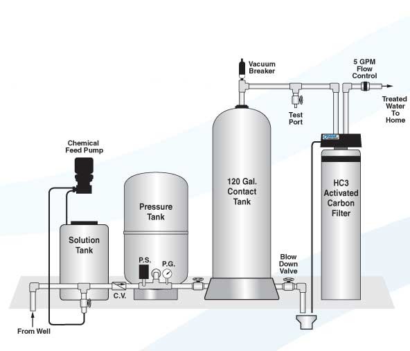

- The feed pump to be wired into the pressure switch. Provide a disconnect. Check voltage and observe appropriate wiring diagram in manual.
- Vacuum breaker is optional.
- Disregard the flow control which is used in low recovery wells only.
- P.S. stands for pressure switch.
- P.G. stands for pressure gauge.
- C.V. stands for check valve and the chemical feed point of injection can be downstream of this valve.


